

Catch Cans - Let's Breathe For a Minute
Who here thinks a catch can is a catch can? I’ll raise my hand. Matter of fact, I've raised my hand many times in my career of doing this. The fact is, there is an actual science behind these things we call a catch can. I mean, to the point where... should we even call it a catch can anymore? The scope of the filtration needs in our engines is a big deal and most of us do not even know why the OEM PCV system was designed the way it was from the factory. The issue, as usual, is too much Internet info and not enough actual experiential info. Let's dive in.
What do you know about your engine and its PCV (pressure crankcase ventilation) system? I am not talking about a 6.2 liter LT4 with a supercharger on your Z06 - I'm talking about the engineering behind it all? The same deep knowledge that whomever the team of engineers were that developed it knows. The assumption is no BUT we can all learn though.
Let's break it down on the GM platform and I use this platform because this has been my 20 plus year career, so it’s best to be honest about what I am talking about. GM typically builds their engines with a low tension oil ring. Now, what this means is that the third slot on the set of pistons, that is your oil control ring pack. It is surrounded by two rings and a very wavy center ring. I am not sure how you even describe it to someone who has not seen it, other than when you were in first grade and you made a cutout in construction paper and then opened it up to be this giant row of continuing art. Kind of like a slinky I guess. Either way, the ring pack is designed to keep oil off the cylinder walls as the piston moves up and down. Now how effectively it does that, well that depends on a lot of things right now.

The stock system is usually set up like this. The crankcase is where the center of the engine is and this is where the pressure or vacuum happens. You have a valley cover plate that has a breather vent port that usually leads to the side of the intake manifold. This is your main point of suction. Now you have the valve covers, which are usually tied together and routed to some point of suction in the cold air intake or close to it. The last point of reference is anything else that needs to breathe, let's say a dry sump car, the air intake bridge then also becomes a point of draw on the dry sump to help alleviate the pressure created in the system.
When you have a constant pressure draw on the crankcase you allow the low tension oil rings to actually seal up along the cylinder walls so oil isn't allowed to pass through and mess with making power or tuning. There have been multiple times where I take a boosted vehicle and run it with and without a closed loop catch can system only to find that without the catch can it blows oil out of the seals and with the catch can it runs smooth as silk. It really is that simple. You gain more power by understanding the actual system that is built by the manufacturer.
So you have vacuum on the crankcase and the valve covers are recycled right back to the vacuum source. Again, taking unwanted air and removing it with vacuum so there are no issues. Same with the dry sump, it gets suction from the vacuum source. Sometimes in a GM system the dry sump and the valve covers are all routed to the same line. It’s fine for stock applications, but only supports so much air movement.

When we design a breather system we are tying every factory line into the breather as if it did not exist on the outside. What we're building is sort of like a factory system, but on steroids. With the added ability to capture oil and water, from things like E85, which contain a lot of water molecules. Keep this in mind that when I am on the dyno with a high horsepower car, I can almost drain water out of the catch can every couple runs. Why? Because the can is doing what it is supposed to be doing. We do not realize most of the time how much oil or water is in the air that moves in our engines. I guess the best way to describe this would be the flu. It travels in the air, and you either filter it or you don't.
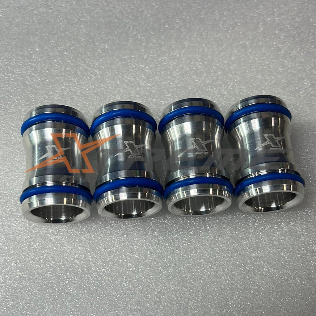
The other mistake being made right now in our industry is that line size tells you how much power you can handle. When I saw this from one manufacturer of catch cans, I almost fell over. They were rating their system by the size of one single line. One! And now recently they have added a second line and now call it double the horsepower! Like as if a 6-7 second drag car with twin turbos would be using this tiny catch can for their power level. This is just not how it works.
Look, I know it is easy to read all of this random Internet stuff out there and think - these guys must know what they are doing. The issue is, you have to actually understand how the engine is made as well to actually design a proper catch can. Engines in general all face the same issues. You have a crankcase, you have intake draw, you have manifold suctions, the list goes on. Stop for a second, and put your own system down on paper. Think about the direction in which air is moving in your engine, and where air might need to be removed. All of this pressure has to go somewhere.
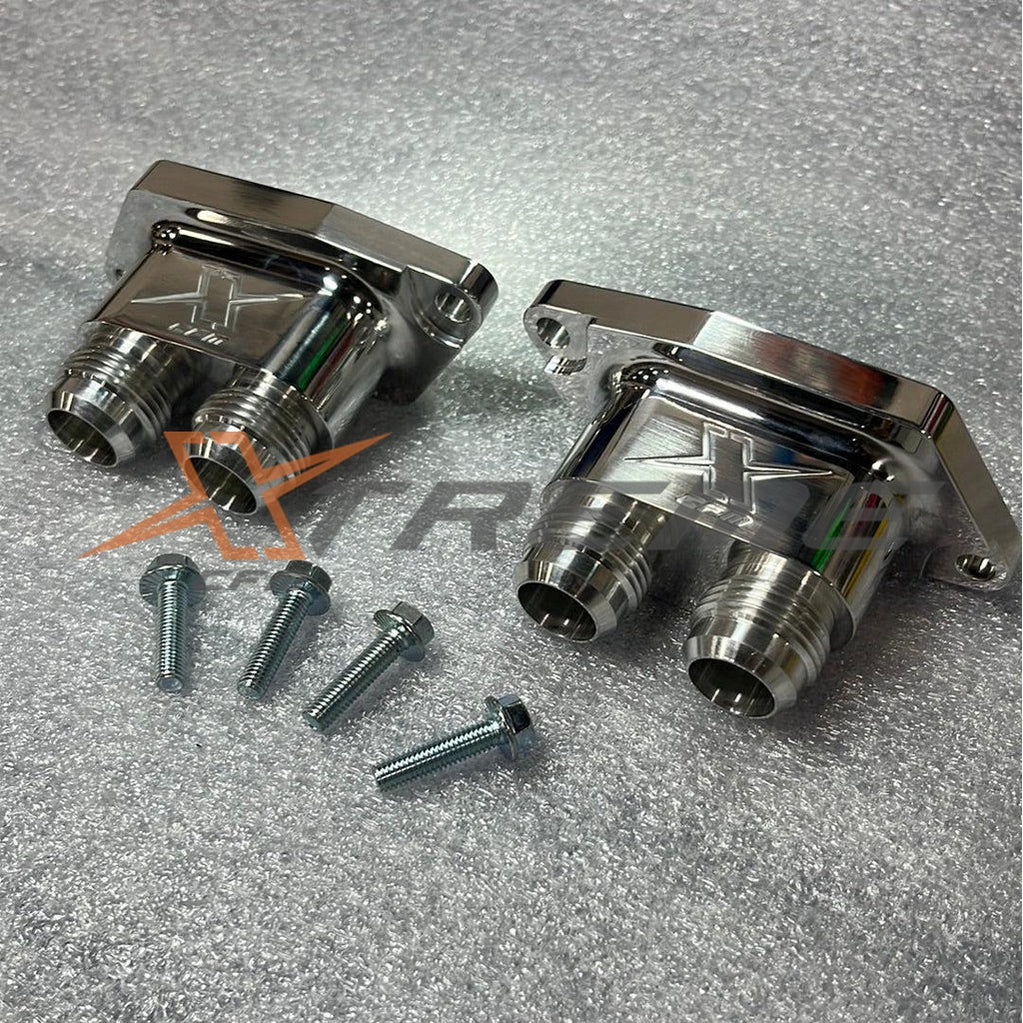
When I build a catch can, I try to do it like the factory, in a closed loop environment. The can has two sides to it, separated by a barrier or wall if you want to say. All the areas that are trying to let air out will all go to one side of the can. And on the other side, the parts of the engine that provide suction all go to the other side. The point of this is that you are using the engine's vacuum to draw all the unwanted pressure and air out of the places you do not want it to be. You also provide constant vacuum on the crankcase, which helps with ring suction and other things. It really becomes that simple. Your catch can now becomes a place where all roads meet and filtering/capture can happen as needed.
- Choosing a selection results in a full page refresh.